Horns & RF Components
We provide competitive pricing on state-of-the-art antenna solutions for the aerospace industry. We are proud to offer an optimum trade off of our low cost, broadband, low mass Horns, Polarizers, OMTs, Transitions, and Reflectors, designed to meet the most demanding RF and mechanical requirements for CubeSats, SmallSats, Orbiters, Landers, and autonomous IOT equipment.
Our products are optimized and manufactured using state-of-the-art techniques ensuring unparalleled performance.
Horns
We offer a selection of standard horn types including spline profiles as well as custom designs (if needed) depending on the antenna SWaP-C requirements. Our solutions provide:
- Low mass and compact design
- Broadband, high gain
- High Power handling
- Low cost
- Short lead times for procurement
The following horn profiles have been standardized depending on the mission requirements. Broadband OMTs can be easily integrated into any flavor.
- Spline shaped radially corrugated walls (high gain profile for global radiation with low cross polarization)
- Axially corrugated choke horn (high performance for compact reflector antennas)
- linearly sloped or spline shaped smooth wall (lower cost solution with lower design & manufacturing complexity)
- Customized sectioned horns (optimal performance specific to a custom set of requirements)
Standardized Horns cover across X, Ku, K, Ka, Q, and V band and can be offered in combined K/Ka and Q/V band options. Our products are optimized and manufactured using state-of-the-art techniques ensuring unparalleled performance.

| P/N | Band | Frequency (GHz) | Typ. Gain (dBi) | Return Loss (dB) | X-Polar (dB) | Flange (mm) | Price | |
|---|---|---|---|---|---|---|---|---|
| Radial Corrugated Horn | RCH4411 RCH4511 RCH4611 RCH4612 RCH4711 RCH4811 RCH4812 RCH4911 | X Ku K K/Ka Ka Q Q/V V | 6.5-8.5 10.25-14.75 17.25-20.75 17.25-30.5 27.5-30.5 37.0-43.0 37.0-53.0 47.0-53.0 | 14-23 | -30 -30 -28 -23 -28 TBC TBC TBC | 23-27 | 28.6 19.4 10.9 10.9 8.76 5.80 5.80 4.85 | Quote |

| P/N | Band | Frequency (GHz) | Typ. Gain (dBi) | Return Loss (dB) | Typ. X-Pol (dB) | Flange (mm) | Price | |
|---|---|---|---|---|---|---|---|---|
| Smooth Wall Horn | SWH4411 SWH4511 SWH4611 SWH4612 SWH4711 SWH4811 SWH4812 SWH4911 | X Ku K K/Ka Ka Q Q/V V | 6.5-8.5 10.25-14.75 17.25-20.75 17.25-30.5 27.5-30.5 37.0-43.0 37.0-53.0 47.0-53.0 | 12-21 | -27 -26 -28 -23 -27 TBC TBC TBC | 20-25 | 28.6 19.4 10.9 10.9 8.76 5.80 5.80 4.85 | Quote |

| P/N | Band | Frequency (GHz) | Typ. Gain (dBi) | Return Loss (dB) | X-Polar (dB) | Flange (mm) | Price | |
|---|---|---|---|---|---|---|---|---|
| Axial Corrugated Horn | ACH4411 ACH4511 ACH4611 ACH4612 ACH4711 ACH4811 ACH4812 ACH4911 | X Ku K K/Ka Ka Q Q/V V | 6.5-8.5 10.25-14.75 17.25-20.75 17.25-30.5 27.5-30.5 37.0-43.0 37.0-53.0 47.0-53.0 | 8-17 | -27 -26 -28 -23 -27 TBC TBC TBC | 20-27 | 28.6 19.4 10.9 10.9 8.76 5.80 5.80 4.85 | Quote |
Polarizers
Horn polarizers come in many forms and can include features to allow single/dual linear or circular polarization. Compact and wideband options exist to meet specific needs. We offered integrated solutions to reduce cost, mass, and envelope while maintaining a high gain profile.
- Wideband Corrugated Polarizer (wideband and inline)
- Septum Polarizer (compact LHCP/RHCP without need for OMT)
- Hybrid (larger overall architecture, but the best performance)

| P/N | Band | Frequency (GHz) | Return Loss (dB) | Insertion Loss (dB) | Axial Ratio | Flange | Price | |
|---|---|---|---|---|---|---|---|---|
| Septum Polarizer | SPL4411 SPL4511 SPL4611 SPL4711 SPL4811 SPL4911 | X Ku K Ka Q V | 6.5-8.5 10.25-14.75 17.25-20.75 27.5-30.5 37.0-43.0 47.0-53.0 | -25 -23 -23 -23 TBC TBC | 0.22 0.28 0.32 0.35 TBC TBC | 0.6 0.8 0.5 0.7 TBC TBC | WR112 WR75 WR51 WR34 WR22 WR19 | Quote |

| P/N | Band | Frequency (GHz) | Return Loss (dB) | Axial Ratio | Flange Width (mm) | Price | |
|---|---|---|---|---|---|---|---|
| Corrugated Polarizer | CPL4411 CPL4511 CPL4611 CPL4711 CPL4811 CPL4911 | X Ku K Ka Q V | 6.5-8.5 10.25-14.75 17.25-20.75 27.5-30.5 37.0-43.0 47.0-53.0 | -27 -25 -23 -23 TBC TBC | 0.5 0.8 0.7 0.5 TBC TBC | 28.50 19.05 12.954 8.636 5.690 4.775 | Quote |
Waveguide Transitions
We offer many types of broadband transitions and waveguide from port to port:
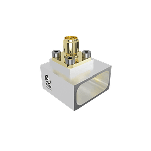
- Coaxial to Waveguide Transitions
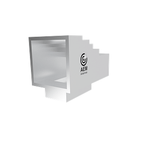
- E-bend, H-bend, Transformers

| P/N | Band | Frequency (GHz) | Return Loss (dB) | Connector Type | Flange | Price | |
|---|---|---|---|---|---|---|---|
| Coax to Waveguide | TSN5411 TSN2511 TSN6611 TSN6711 TSN7811 TSN7911 | X Ku K Ka Q V | 6.5-8.5 10.25-14.75 17.25-20.75 27.5-30.5 37.0-43.0 47.0-53.0 | -23 -23 -23 -23 TBC TBC | N SMA K (2.92mm) K (2.92mm) V (1.85mm) V (1.85mm) | WR112 WR75 WR51 WR34 WR22 WR19 | Quote |
Orthomode Transducers and Junctions
The following stand-alone Orthomode Transducers (OMT) and Orthomode Junctions (OMJ) are available. Reach out if a specific dual or multi-polarization configuration is required for your antenna.
- Orthomode Transducers
- Orthomode Junctions with integrated filters (contact us)

| P/N | Band | Frequency (GHz) | Return Loss (dB) | Port Isolation | Flange Ports | Price | |
|---|---|---|---|---|---|---|---|
| Orthomode Transducer (OMT) | OMT3411 OMT3511 OMT3611 OMT3711 OMT3811 OMT3911 | X Ku K Ka Q V | 6.5-8.5 10.25-14.75 17.25-20.75 27.5-30.5 37.0-43.0 47.0-53.0 | -25 -25 -25 -25 TBC TBC | -50 -45 -45 -50 TBC TBC | WR112 WR75 WR51 WR34 WR22 WR19 | Quote |
Filters and Diplexers
We offer high power, low loss compact waveguide filters for common bands. A customize filter or diplexer can be modified from our catalog for a specific set of requirements including transmit/receive isolation and higher order mode filtering.
- Low Pass filters
- Band Pass Diplexers and Multiplexers
- High pass filters
- PIM Chokes
Contact us to discuss your filter requirements and to verify with our design catalog.
Integrated Antenna Architectures
A functional block diagram of our generic antenna architecture is provided. Our team can provide highly integrated solutions for further mass and envelope reductions.

Some of the various components and modules offered is summarized below.
| Description | Critical Features | |
|---|---|---|
| Horn | A rotationally symmetric horn to support all polarizations | • Radiator • Throat matching section to increase bandwidth • Flare features to increase gain and reduce cross-polarization |
| Orthomode Transducer (OMT) | An Asymmetric OMT is used to create vertical and horizontal polarization components | • Port symmetry to reduce higher order mode content • Matching elements to increase bandwidth |
| Polarizer | A septum, corrugated, or hybrid component used to produce circular polarization | • Phase stable across a wide band • Precisely machined with tight tolerances in sensitive regions |
| Transition | Coax to waveguide transition | • Tuning elements on and around the probe for wideband operation |
For integrated solutions, contact our team to discuss possible options.
If you are interested to learn more about the different feed horn architectures, you may want to check out our article on Selecting the Best Horn Antenna.
Antenna Simulation
Our custom in-house reflector and feed simulation tools (RECO) can quickly optimize an antenna.
Frequently Asked Questions:
Antenna Product Experts
✔ Each component performance is as predicted using aerospace manufacturing precision
✔ Our products maximize gain, wide bandwidth, and efficiency
✔ Each component is carefully designed by experienced antenna & RF component specialists


